Home › Unlabelled ›
Symbol For Motor In Circuit Diagram / 31 Amazing Motor Circuit Symbol Electrical Wiring Diagram Symbols Pdf Motor Control Circuit Diagram Pdf Three Phase Motor Control Circuit Diagram With 31 Amazing Motor Circuit Symbol Interesting Mcc Singleline Diagrams With - The standard circuit component symbols and circuit symbols are important for circuit schematic diagrams.
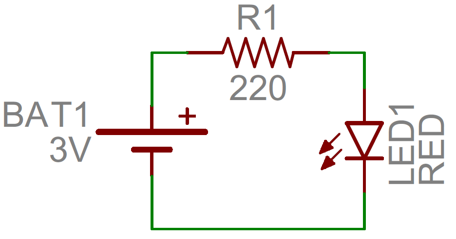
Symbol For Motor In Circuit Diagram / 31 Amazing Motor Circuit Symbol Electrical Wiring Diagram Symbols Pdf Motor Control Circuit Diagram Pdf Three Phase Motor Control Circuit Diagram With 31 Amazing Motor Circuit Symbol Interesting Mcc Singleline Diagrams With - The standard circuit component symbols and circuit symbols are important for circuit schematic diagrams.. Circuit or schematic diagrams consist of symbols representing physical components and lines representing wires or electrical conductors. I'd like to draw a dc motor like this: Have applications in motors, and tank circuits. It can be used for a zero potential reference point from where current is measured. We need this circuit diagram in every where in the electrinics.
A final means of describing an electric circuit is by use of conventional circuit symbols to provide a schematic diagram of the circuit and its components. Click on each link given below to view the the wire is coiled on a soft iron core. These electrical and electronics circuit symbols are used in circuit diagrams to explain how a circuit is interconnected. Have applications in motors, and tank circuits. The symbols used to make circuit diagrams are standardized on an international level.
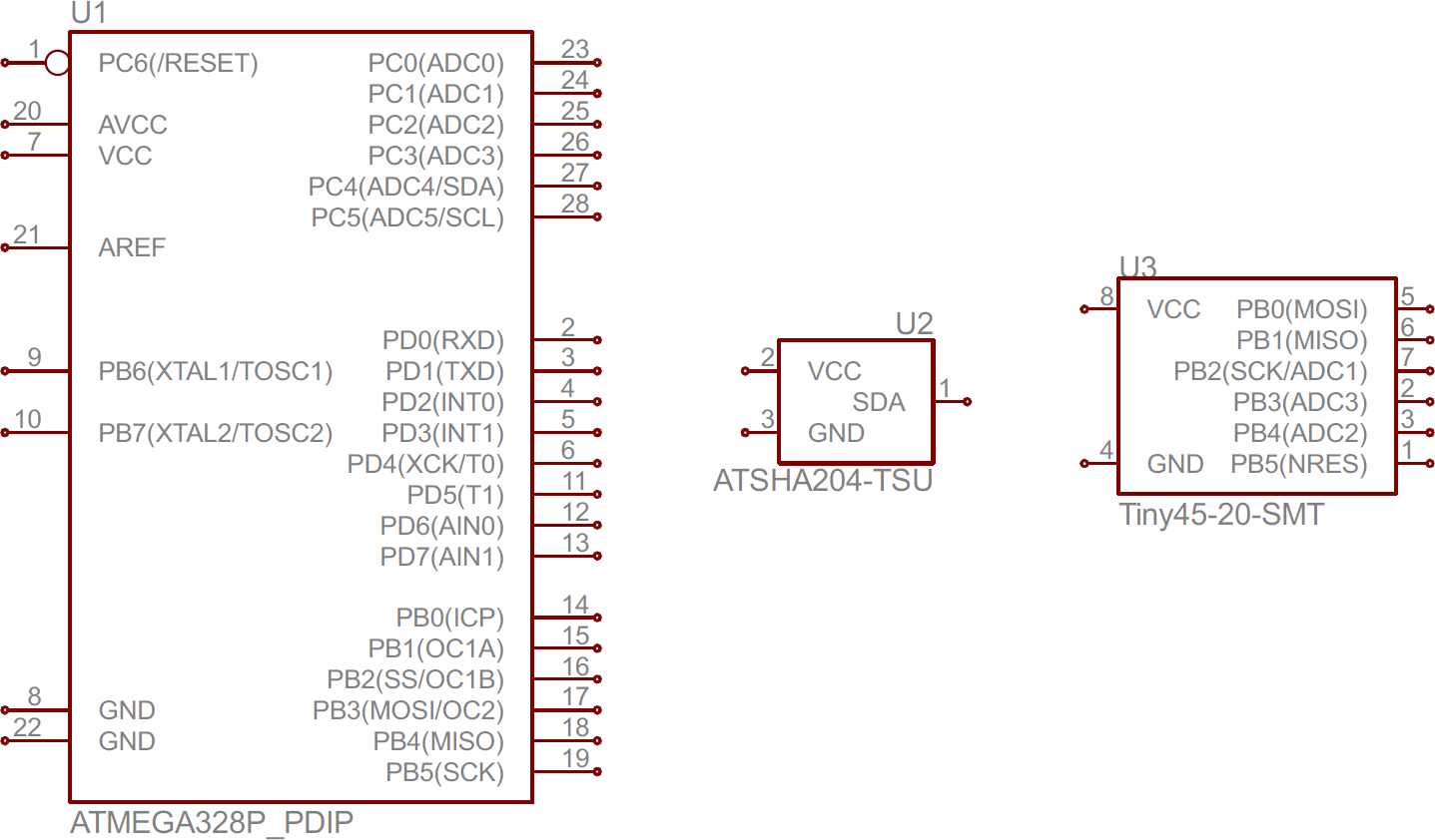
How To Read A Schematic Learn Sparkfun Com from cdn.sparkfun.com Circuit symbols and circuit diagrams. It is not difficult to learn the basic symbols. In order to learn how to read a circuit diagram, it is necessary to learn what the schematic symbol of a component looks like. The actual layout of the components is usually quite different from the circuit diagram. A ground symbol (iec symbol 5017) identifies a ground terminal. It looks like there's no symbol for motors in circuitikz. Electrical symbols and electronic circuit symbols are used for drawing schematic diagram. How i draw those symbols?
To build a circuit you need a different diagram showing the layout of the parts on stripboard or printed circuit board.
How i draw those symbols? This enables anyone to read a circuit diagram and know what it. In electronics we use maps called circuit diagrams as a graphical representation of the connections and components in a circuit. Electrical symbols are the most commonly used symbols in circuit diagramming. A circuit diagram can be defined as a graphical representation of an electronic circuit. Circuit symbols are used in circuit schematic diagrams which show how a circuit is connected together electrically. Now as shown in the circuit diagram the 555 circuit here is to generate clock or the square in binary counter q0,q1 and q2 (1+2+4) pins will be high. Electrical circuit symbols on chalkboard. Should have a fuse on control circuit and possibly show a transformer for control circuit in which more often than not one is used. Designation of components in the wiring diagram. Remote control circuit with optocoupler schematic circuit diagram. Electrical symbols and electronic circuit symbols are used for drawing schematic diagram. Instantaneous braking of dc motors schematic circuit diagram.
I'm using circuitikz to create an electric circuit diagram. While some symbols are identical (the toggle switch, for. Take the ac motor control circuits (ac electric circuits) worksheet. Without microphone we can't think electronics. Instantaneous braking of dc motors schematic circuit diagram.
Posistion Selector Switch Wiring Diagram 2 Wiring Diagram Solve Explorer Solve Explorer Pmov2019 It from machineryequipmentonline.com A final means of describing an electric circuit is by use of conventional circuit symbols to provide a schematic diagram of the circuit and its components. Should have a fuse on control circuit and possibly show a transformer for control circuit in which more often than not one is used. A circuit diagram, or a schematic diagram, is a technical drawing of how to connect electronic components to get a understanding how a circuit diagram works can be a bit tricky. Remote control circuit with optocoupler schematic circuit diagram. Circuit diagrams can be created with thousands of possible shapes and icons and lucidchart's. Electrical circuit symbols on chalkboard. Follow along with karen as. Can you imaging, i want to buy just dc motors for a junky project am not getting it.
Circuit symbols are used in circuit diagrams which show how a circuit is connected together.
Without microphone we can't think electronics. Standardized symbols make diagrams easier to read. There are also pressure and current coils such that when. Electrical symbols and electronic circuit symbols are used for drawing schematic diagram. It looks like there's no symbol for motors in circuitikz. Instantaneous braking of dc motors schematic circuit diagram. Circuit symbols overview resistors capacitors inductors, coils, chokes & transformers diodes bipolar transistors field today, circuit symbols and their usage has been pretty much standardised. A ground symbol (iec symbol 5017) identifies a ground terminal. We need this circuit diagram in every where in the electrinics. Chemical and process engineering solution contains variety predesigned process flow diagram elements relating to instrumentation, containers, piping the vector stencils library hydraulic pumps and motors contains 74 symbols of hydraulic pump vector stencils, hydraulic motor symbols for. Electrical circuit symbols on chalkboard. Create electrical circuit diagrams and schematics with electrical symbols provided by smartdraw software. I'd like to draw a dc motor like this:
Now as shown in the circuit diagram the 555 circuit here is to generate clock or the square in binary counter q0,q1 and q2 (1+2+4) pins will be high. Amplifiers (denoted by triangle shapes) increase the output signal in your circuit. Electrical symbols and electronic circuit symbols are used for drawing schematic diagram. Circuit symbols are used in circuit diagrams which show how a circuit is connected together. Circuit symbols and circuit diagrams.
How To Read A Schematic Learn Sparkfun Com from cdn.sparkfun.com The symbols used to make circuit diagrams are standardized on an international level. In electronics we use maps called circuit diagrams as a graphical representation of the connections and components in a circuit. This enables anyone to read a circuit diagram and know what it. All circuit symbols are in standard format and can be used for drawing schematic circuit diagram and layout. The original layout of electronic components is to build an actual electronic circuit we need different diagram showing the layout of the parts on printed circuit board (pcb). It looks like there's no symbol for motors in circuitikz. Not like a layout or block diagram, an electronic. This switch can be wired up as a reversing switch for a motor.
Remote control circuit with optocoupler schematic circuit diagram.
A circuit diagram, or a schematic diagram, is a technical drawing of how to connect electronic components to get a understanding how a circuit diagram works can be a bit tricky. We need this circuit diagram in every where in the electrinics. These electrical and electronics circuit symbols are used in circuit diagrams to explain how a circuit is interconnected. Electrical symbols are the most commonly used symbols in circuit diagramming. Circuit symbols are used in circuit diagrams which show how a circuit is connected together. Chemical and process engineering solution contains variety predesigned process flow diagram elements relating to instrumentation, containers, piping the vector stencils library hydraulic pumps and motors contains 74 symbols of hydraulic pump vector stencils, hydraulic motor symbols for. In electronics we use maps called circuit diagrams as a graphical representation of the connections and components in a circuit. Instantaneous braking of dc motors schematic circuit diagram. How i draw those symbols? Click on each link given below to view the the wire is coiled on a soft iron core. The electrical systems in vehicles contain a wide array of electric designation codes devices, parts or symbols are labeled in circuit diagrams with a letter and a bosch makes block diagrams for further systems in a great number of motor vehicles available in. Not like a layout or block diagram, an electronic. Circuit diagrams can be created with thousands of possible shapes and icons and lucidchart's.